Trimbuphone
2021 — 2 min read
Overview #
I developed the Trimbuphone for my junior design class. The individual assignment was simply to make circuit using a 555 timer and then design and assemble it on a PCB. I personally also took on the challenge to develop a professional enclosure.
Download the full report here.
A Complete Synthesizer #
I designed the Trimbuphone to be a fully functioning synthesizer. While it might be very limited, it has a complete analog output and two octaves of range with tunable notes. There is also an adjustable volume knob and built in speaker to enjoy the device without any headphones.
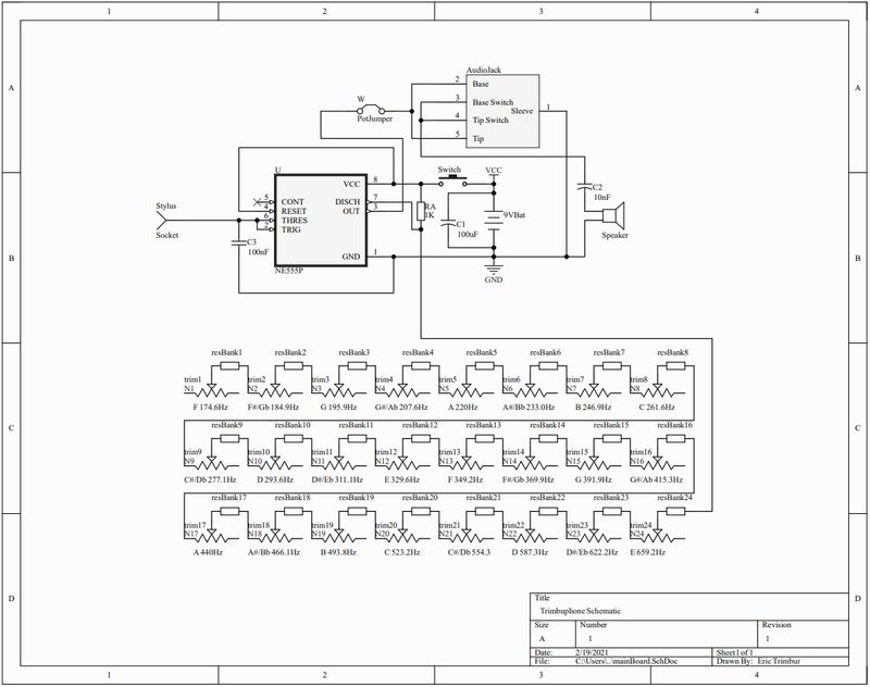
Schematic Design #
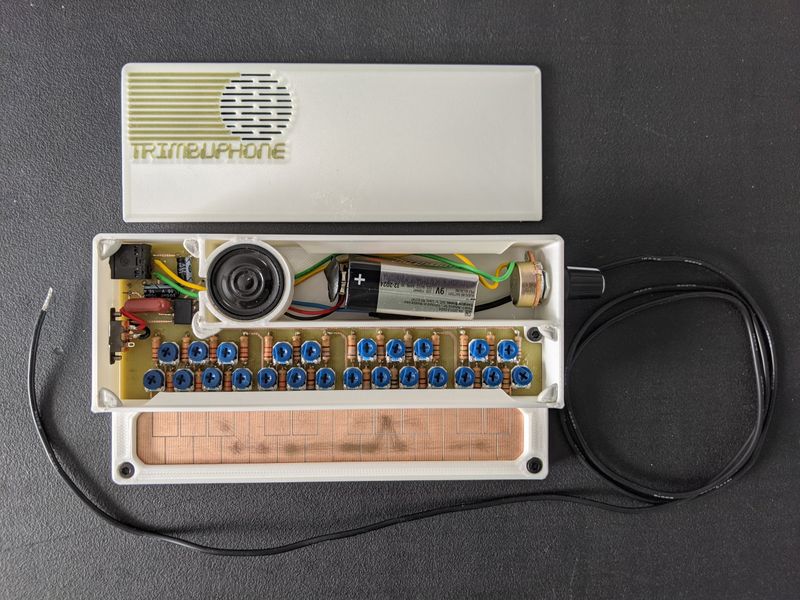
The schematic runs the 555 timer in an astable configuration. There is no output until the circuit is completed by the user touching the stylus to one of the exposed pads connected to the resistor bank. I designed the resistor bank to be made of resistor potentiometer pairs. The resistors gave most of the tuning, allowing me to chose smaller valued potentiometers to give the finest control of the exact frequency.
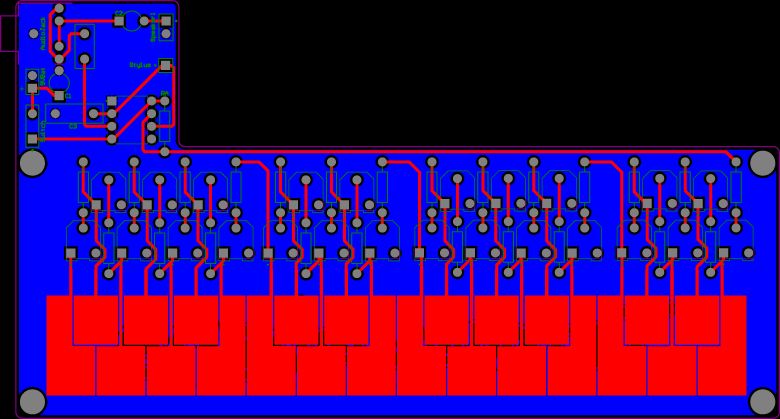
PCB Design #
I designed the PCB in Altium Designer. The user interacts directly with the exposed pads in the shape of a keyboard. I designed this in a vector graphics software and later imported it into Altium and assigned them the proper nets. I layed out the tuning pots in the same layout as the keyboard to make it visually easy to tune. I also added mounting holes for the enclosure and a large cutout to give room to the battery and speaker.
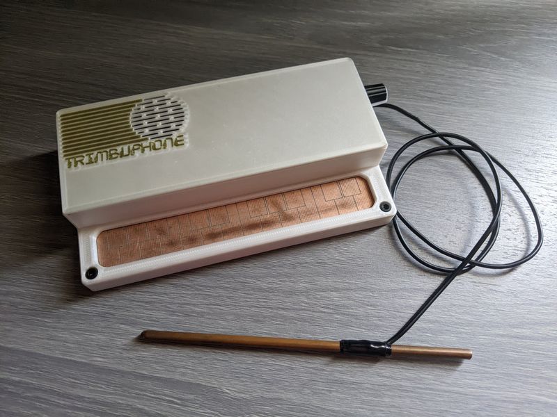
Custom 3D Printed Enclosure #
I designed the enclosure in Fusion 360 and 3D printed it on my personal printer. The enclosure includes mounts and holes for the audio jack, volume potentiometer, and power switch. The speaker was given a secure mount and slots to let the sound through. The user is left to only see the pads they need to interact with.