Rubik’s Cube Solver
2022 — 2 min read
Overview #
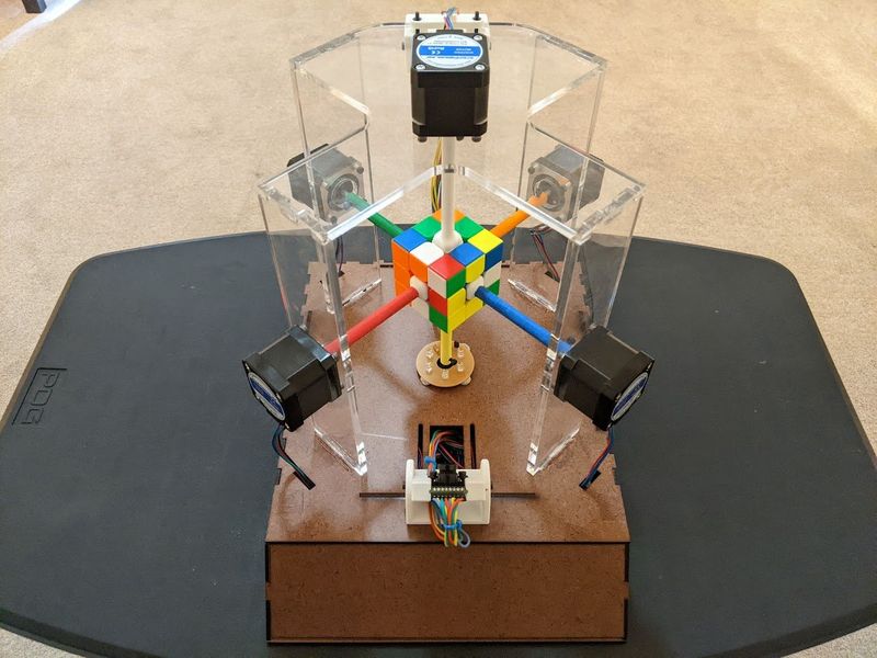
I collaborated with three engineers to design and build a robot able to autonomously solve a Rubik’s Cube. This project represents a semester’s worth of work in my senior design class. My personal responsibilities included:
- system design
- PCB design
- manufacturing
- motor control
Download the full report here.
System Design #
I led system design efforts on the team. We simplified the robot's mechanical design by giving each axis of movement on the cube its own motor. Then we positioned cameras at each corner of the cube to retrieve full color information. I separated the computation of the motor movement from the computer vision and solving algorithm. I implemented this by dedicating a microcontroller just to motor control. My decision granted true parallelism and afforded us maximal flexibility during development.
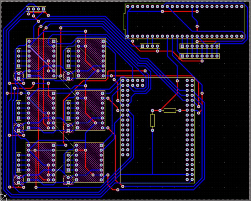
Custom PCB #
I assumed responsibility for PCB design and routing using a teammate's schematics. I leveraged Altium Designer to create a design compatible with our tight timeline. Time necessitated that the board be milled in-house. So I connected all traces to through-hole components on the bottom layer. Then, I minimized the vias that we would have to fill. This design ultimately helped keep the project on pace for delivery.
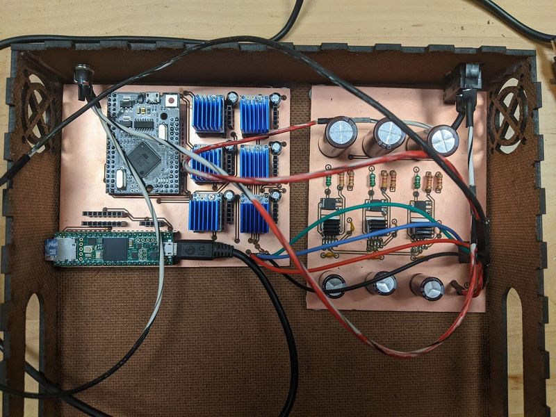
Hands on Manufacturing #
I milled the boards on our makerspace's mill. We filled vias, soldered on components, and validated the board with a digital multimeter. I designed the enclosure and other mechanical components in Fusion 360. I either laser cut or 3D printed each component.
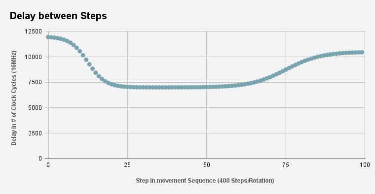
Optimized Movement #
I was especially dedicated to writing firmware to optimize the motor movement. I designed a speed profile to achieve precise movement using stepper motors. The initial speed is limited by how fast the motor can start without skipping steps. A faster speed is possible through gentle acceleration. Stopping too fast can also result in skipped steps. As a countermeasure, I added a deceleration curve to reduce the axis' momentum. Finally, I developed a testing procedure to tune the parameters of the equation I developed. I implemented the movement curve in custom-embedded C firmware. Our final result was a 19% increase in motor movement compared to constant speed movement.
Gallery #
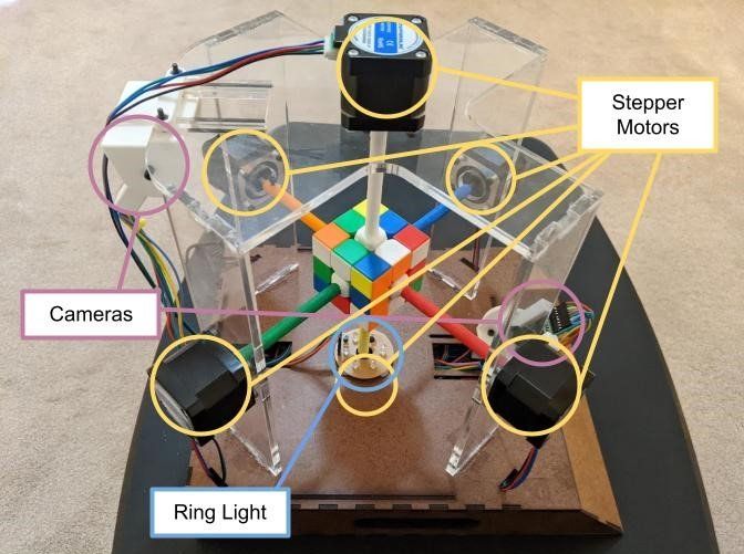
Labeled Side View
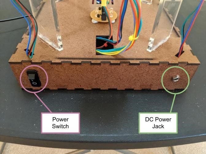
Labeled Back View
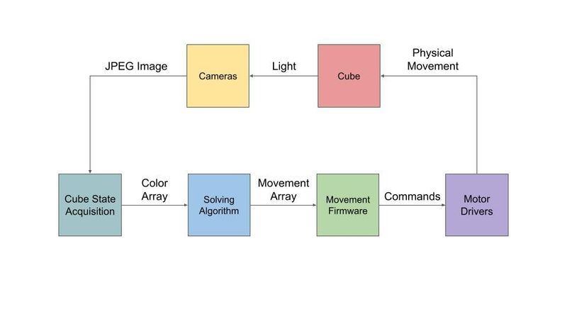
Data Flow Diagram
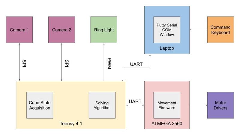
System Block Diagram
Back to my projects